Improved precision with German-standard actuators and minimized mechanical parts using octanal profiles.
Results Achieved
High-speed transfer with consistent precision
Improved reliability and maintenance efficiency
Reduced mechanical parts and assembly time
Modular Slim Transfer Conveyor
A lightweight and modular transfer conveyor designed for fast operation and future scalability.
Components Used:
Overhead structure and adaptable mounting – F.EE GmbH
Challenge
Slim Simple
CONCEPT
24 m/min
HIGH SPEED
50kg
WEIGHING Support Roof Part
Solution
Optimized layout and lightweight octagonal profiles improved the transfer function, enabling higher operating speeds and modular length extensions.
Results Achieved
Lightweight and clean mechanical design
Future-ready modular expansion capability
Fast cycle time
Flexible Overhead Transfer
An overhead transfer solution designed for lean production and multi-model handling within a single system.
Components Used:
Overhead structure and adaptable mounting – F.EE GmbH
Challenge
4.5m/2.25s
SPEED 2 m/s
10kg
WEIGHING Support Roof Part
Solution
We re-engineered the machine structure using modular aluminum profiles to replace conventional heavy steel frames. By integrating precision German-standard actuators, the system achieved smooth and reliable motion with significantly lower overall mass.
Results Achieved
One system supporting multiple product models
Faster changeover and higher production flexibility
Reduced mechanical complexity and weight
Auto Measuring Machine
An upgraded inspection machine designed to improve efficiency while significantly reducing system weight.
Components Used:
Structural frame – F.EE GmbH
Linear motion and positioning – IMI Bahr Modultechnik
Challenge
2m/1s
SPEED
10 μm
REPEATABILITY
Solution
Octagonal aluminum profiles enable flexible, tool-less reconfiguration, reducing custom parts and facilitating quick adaptation to various workpieces.
Results Achieved
Significantly reduced machine weight
Easier installation and maintenance
Improved flexibility for future modifications
Simulation References
WHY SIMULATION MATTERS ?
Validate Performance
Ensure the system works as expected before manufacturing
Reduce Engineering Risk
Identify potential issues early in the design phase
Optimize Motion & Cycle Time
Improve productivity and efficiency
Improve Structural Design
Analyze loads and stress on critical components
Simulation Case Study
Full Loop Automation
Simulation was used to analyze and improve the system performance of a robotic production loop
Cycle Time Improvement
Initial Cycle Time
49 SEC
Cycle Time Reduced
20%
Final Cycle Time
39 SEC
Initial Concept
Two robots were introduced to replace manual operations.
Cycle Time
49 SEC
Final Concept
Robot sequencing was optimized to reduce idle time, while three transfer units were added to improve material flow
Cycle Time
39 SEC
4 Face Grinding Robot
Simulation was used to optimize material flow before implementation
Cycle Time Improvement
Initial Cycle Time
32 SEC
Cycle Time Reduced
10%
Final Cycle Time
29 SEC
Initial Concept
Initial layout with 1 buffer unit
Cycle Time
32 SEC
Final Concept
Optimized by increasing buffers from 1 to
3 units to stabilize material flow
Cycle Time
29 SEC
Our Simulation Capabilities
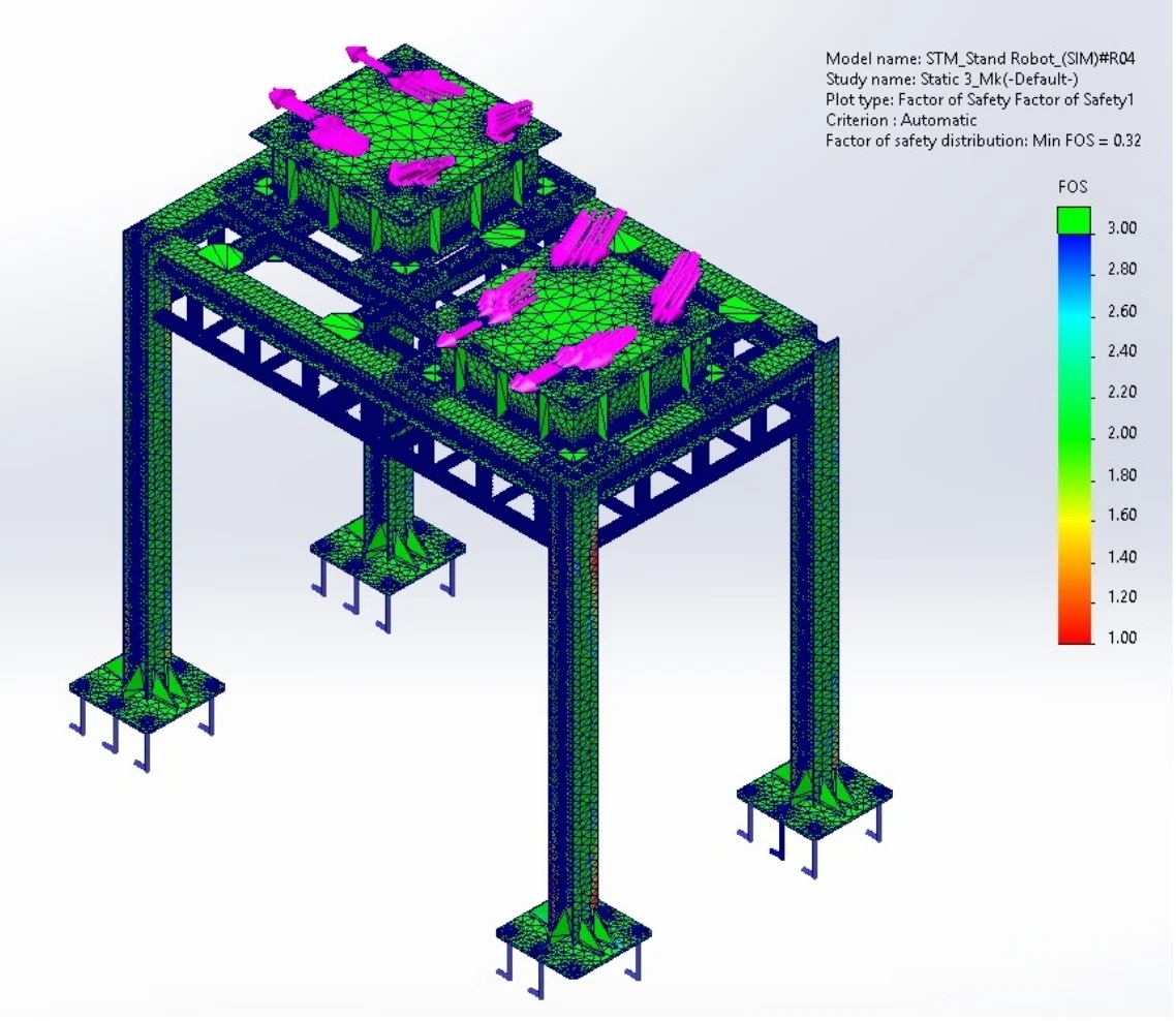
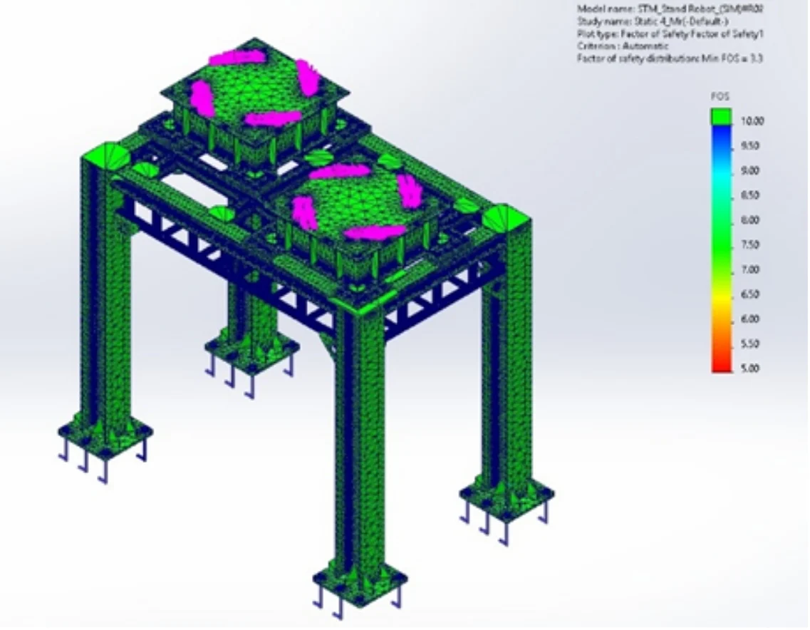
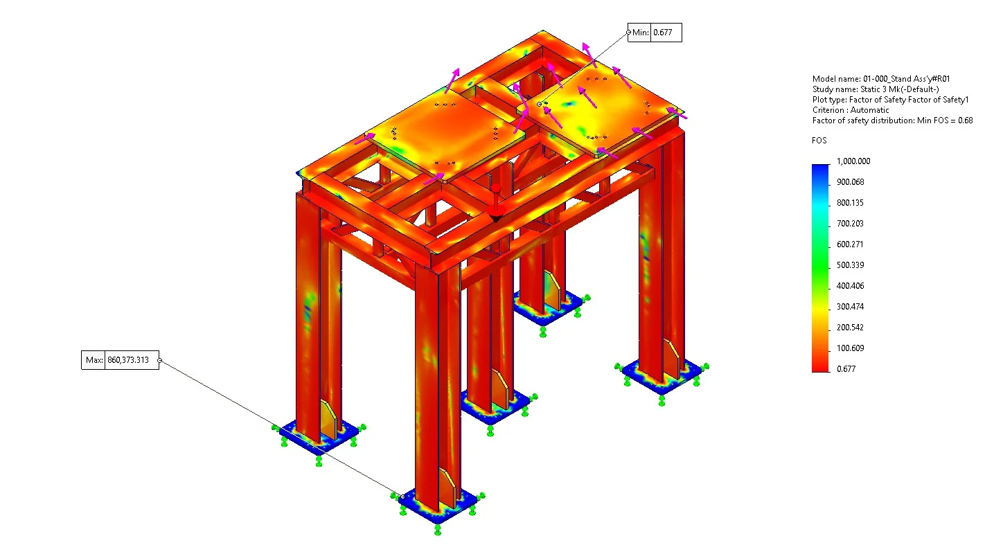
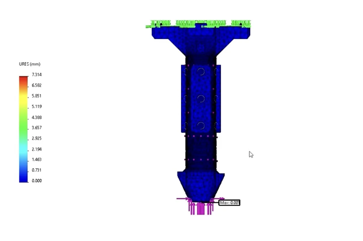
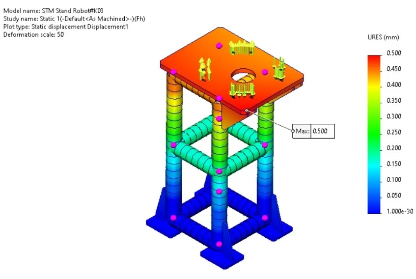
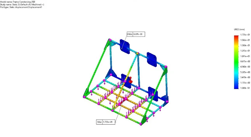
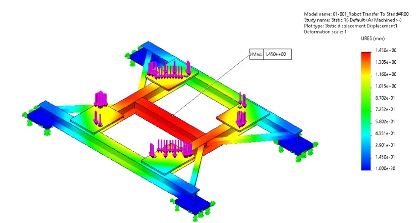
Static Simulation
Finite element analysis validated structural integrity under maximum load conditions before implementation.